Development of selfmade circular patch antennas for GNSS and satellite communication
Artificial intelligence (AI) is opening up new possibilities in antenna development. This blog post shows how you can use AI tools such as ChatGPT, Gemini, Perplexity, or Deepseek to develop your circular patch antennas for different frequency ranges.
Frequency ranges and antenna types
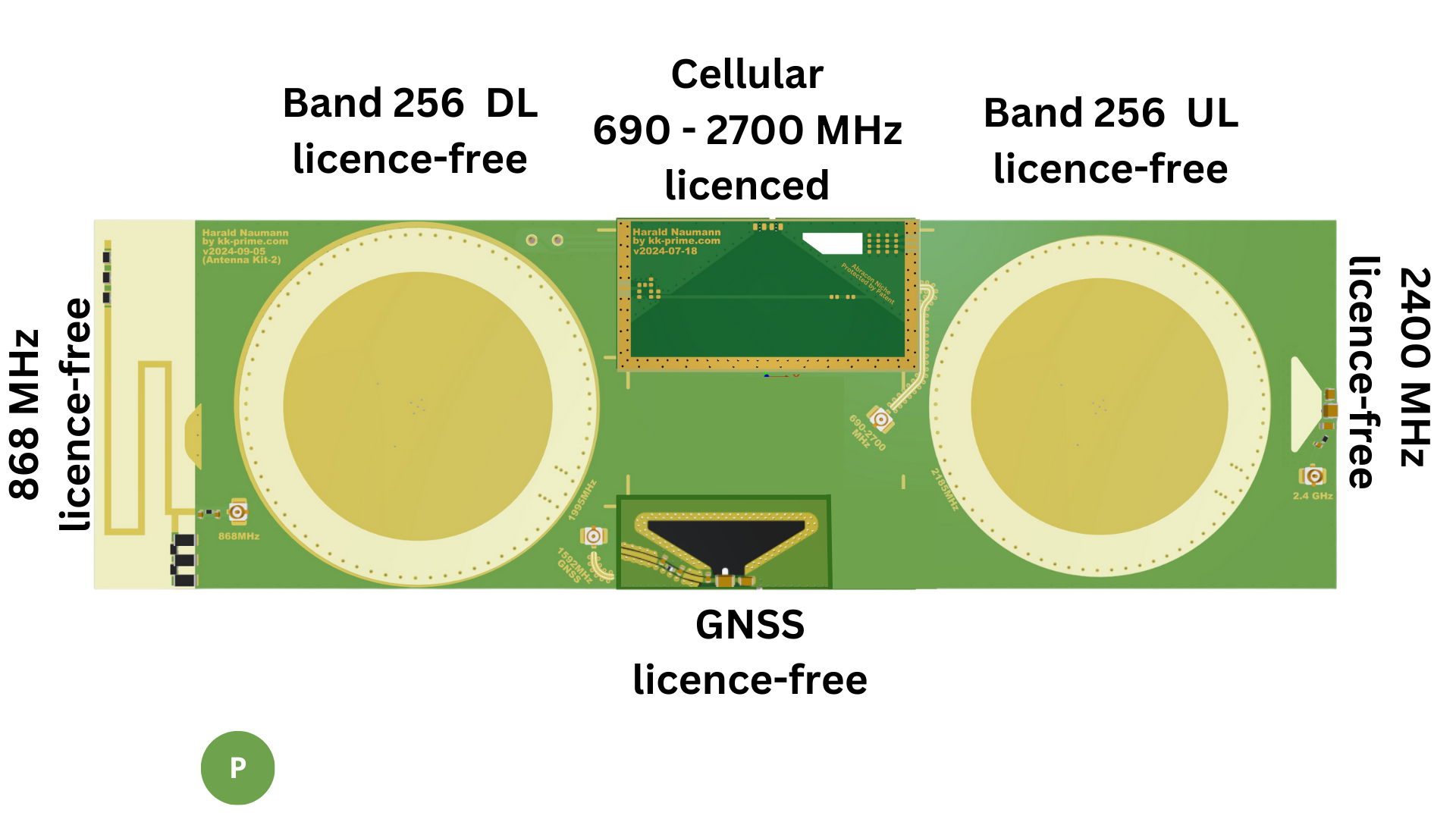
The Antennity evaluation kit contains patch antennas for the following frequency ranges:
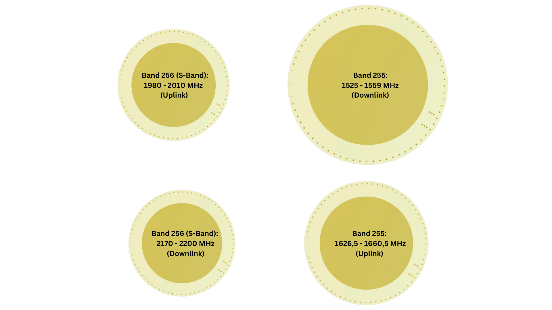
- Satellite band 255 (Upper L-band): 1525 – 1559 MHz (downlink), 1626.5 – 1660.5 MHz (uplink)
- WiFi/Bluetooth: 2400 – 2483.5 MHz
You can choose your antennas for the following bands:
- GNSS (GPS L1): 1575.42 MHz
- Satellite band 23 (S-band): 1980 – 2010 MHz (uplink), 2170 – 2200 MHz (downlink)
- Band 256 (S-band): 1980 – 2010 MHz (uplink), 2170 – 2200 MHz (downlink)3
These antennas cover a frequency range from around 1.5 GHz to 2.4 GHz.
Procedure for antenna development
- Purchase the Antennity evaluation kit with 13 antennas.
- Take the diameters of the patch antennas for band 256 UL and DL from the Altium files.
- Use AI tools to calculate the diameters for other frequency bands.
- Consider the material properties of the FR4 substrate (dielectric constant 3.8-4.517, dissipation factor 0.012-0.0351).
- Transfer the data to the AI to calculate new antenna diameters.
- Create the layout and produce prototypes.
- Measure the centre frequency of both feed points with a vector network analyser (VNA).
- Optimise iteratively until the requested precision is achieved.
Advantage of the 90-degree phase shifter
A key advantage of our antenna design is the use of a 90-degree phase shifter. This enables:
- Perfect circular polarisation regardless of the antenna position in the PCB
- Avoidance of polarisation losses that can occur with single-feed antennas
- Greater precision and reliability in signal transmission
Precision as the ultimate goal
At Antennity, we strive for maximum precision. We achieve this by:
- Using two feeding points per patch antenna
- Using simulation to precisely calculate the feeding point positions
- Iterative optimisation of the antenna diameters based on VNA measurements
- Consideration of housing influences in the simulation
AI-supported calculations
The AI supports the following calculations:
- Antenna diameters for different frequency bands
- Positioning of the feed points
- Dimensioning of the 50-ohm cables
- Matching to different FR4 materials
Note: If you have a small budget, you can have the antennas simulated by the Antennity team, including the enclosure.
Matching the phase shifter
The matching of the phase shifter to the PCB can be carried out inexpensively by the Antennity team. The customer hands over their PCB, the team carries out the matching, measures the antennas and documents the components for matching.
Conclusion
Developing your own PCB antennas is entirely possible with the right expertise and AI support. Antennity not only offers the necessary evaluation kit, but also free layouts and support for a fee. Our approach enables developers to realise precise and cost-effective antennas for various applications. Antennity sees itself as the ‘Linux of antenna development’ – open, flexible and supportive for anyone who wants to develop their own antenna solutions. If desired, all steps towards any antenna can be assisted remotely.


0 Comments